Detailed explanation of tee pipe knowledge: large-scale project procurement guide
Table of contents
- Introduction
- What is a tee
- Types of tees
- Equal diameter tees vs reducing tees
- Tee size table
- Implementation standards for galvanized tees
- Installation steps for tees
- Applications of tees
- Tees vs reducing pipes
- Summary
Introduction
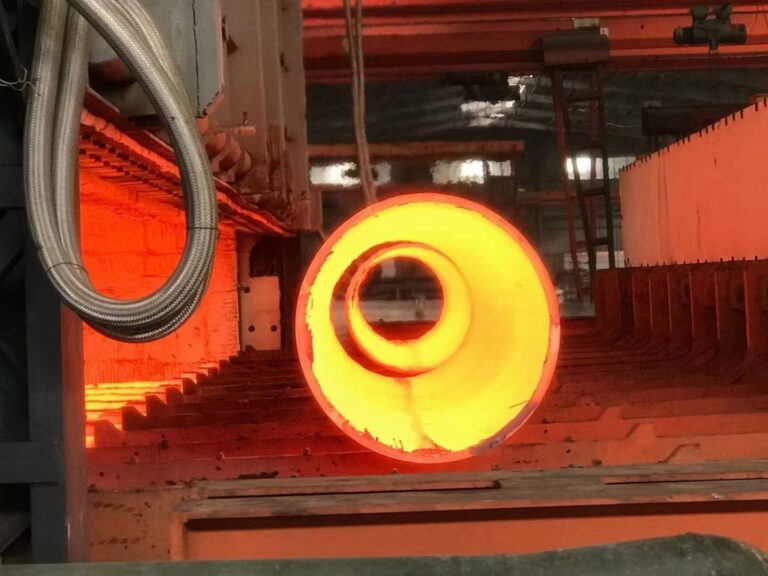
Tee pipes play an important role in the transportation of liquids and gases in the pipe network. There are various material choices.
Depending on the different transport media, cast steel, cast copper, plastic, cast iron, cast aluminum or glass may be used. Tee pipes are widely used in many fields. How much do you know about their types, structures and uses?
Through this article, we will introduce the tee pipe in detail, compare it with the reducer, and its classification and application.
This knowledge is also the standard for large-scale project procurement. I hope it can provide some suggestions and help to everyone.
What is a tee
Tee, or Y-type joint, is named because of its shape similar to the letter “Y”.
It is mainly used to bring the fluids of two or three pipes together, or to divert the fluid in one pipe to two or three pipes.
Tee is widely used in water heating, air conditioning and ventilation systems in homes, industries and public facilities.
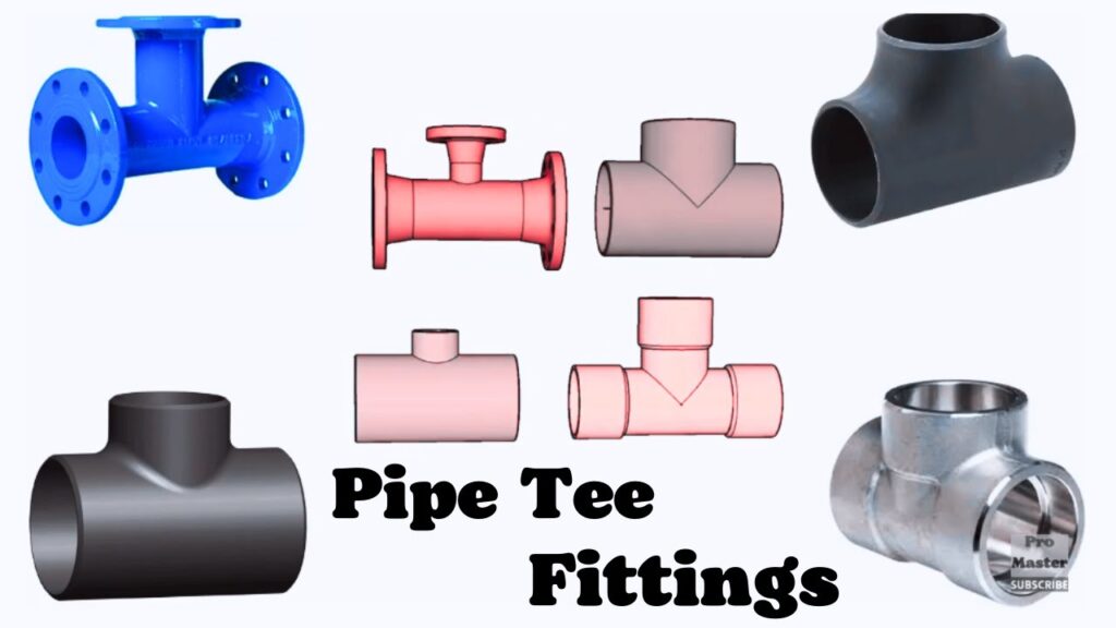
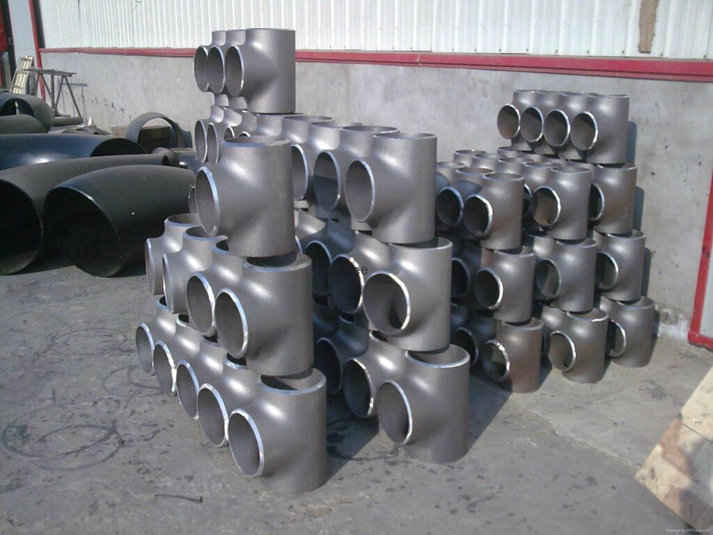
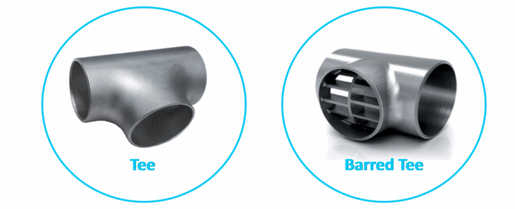
Types of tees
Tees can be divided into different types according to their shape and the number of connection ports.
In terms of shape, the most common types are Y-type tees, T-type tees, and cross-type tees. In terms of the number of connection ports, they include double-connection tees, triple-connection tees, and quad-connection tees.
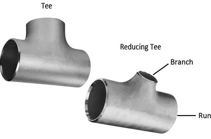
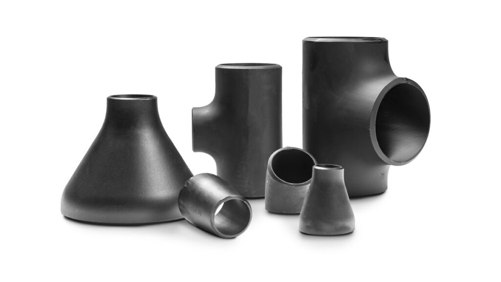
Equal diameter tees vs reducing tees
| Characteristic | Equal Tee (Straight Tee) | Reducing Tee (Reducer Tee) |
| Branch/Run Relationship | Branch diameter equals run diameter (e.g., 6″ x 6″ x 6″). | Branch diameter smaller than run diameter (e.g., 6″ x 6″ x 4″). |
| Flow Path Design | Symmetrical flow split; uniform pressure distribution. | Asymmetrical flow; potential for turbulence at reduction. |
| Standard Reference | ASME B16.9 (Factory-Made Wrought Buttwelding Fittings) | ASME B16.9 (Includes dimensional standards for reducers). |
| Dimensional Marking | Single size designation | Three sizes: Run x Run x Branch |
| Pressure Drop | Lower at branch due to matching diameters. | Higher at reduced branch (flow velocity increases). |
| Primary Applications | • Equal flow division. • Main pipeline headers with identical branches. | • Branch lines with lower flow demand. • Connections to smaller valves/instruments. |
| Material Efficiency | Higher material usage (consistent wall thickness). | Lower material volume at reduced branch. |
| Fabrication Complexity | Simpler (consistent bore machining). | Complex (requires concentric/eccentric transition geometry). |
| Hydraulic Stress | Uniform stress distribution at junctions. | Stress concentration at branch-to-run transition zone. |
| Welding Preparation | Uniform bevel profile across all ends. | Differential bevel angles at branch vs. run connections. |
| Industry Examples | Cooling water distribution; HVAC supply trunks. | Chemical process lines (main header to instrument taps). |
Tee size table
The size of equal-diameter tees is usually determined by their nominal diameter DN, such as DN25, DN50, DN100, etc. The size of reducing tees is determined by the diameters of the interfaces at both ends.
The following are some common tee size data (unit: mm):
- DN25 equal-diameter tee: outer diameter 48.3mm, wall thickness 3.6mm, tee cross tube length 89mm, tee total length 117mm.
- DN50 equal-diameter tee: outer diameter 60.3mm, wall thickness 4.0mm, tee cross tube length 114mm, tee total length 152mm.
- DN100 equal-diameter tee: outer diameter 114.3mm, wall thickness 6.0mm, tee cross tube length 184mm, tee total length 261mm.
The size of reducing tees varies depending on the different diameters of the pipes they connect.
For example, for a reducing tee with a 25mm diameter on one end, the other end may be 32mm, 40mm, etc. The specific size needs to be selected according to the actual situation.

Implementation standards for galvanized tees
ANSI/ASME B16.9-2007 “Welded and Seamless Steel Fittings for Industrial Use”: This standard was developed by the American Society of Mechanical Engineers (ASME) and covers the design, manufacturing and inspection requirements for industrial steel fittings, including connectors such as tees.
International standards such as JIS B2311-2009 “Standard Specification for Common Steel Fittings” and DIN 2440-2004 “Non-alloy Steel Fittings” provide detailed regulations on the design, material selection, manufacturing process and quality control of galvanized tees.
Installation steps for tees
The installation of a tee with three fixed ends is relatively simple, but you need to follow the steps strictly:
- First, make sure the ports of the three pipes to be connected are clean and free of obstacles.
- Connect the three pipes to the three ports of the tee respectively, and ensure that the connection is tight.
- Use screws to fix the pipes and the tee firmly to avoid deformation or damage of the pipes due to over-tightening.
- After installation, check whether the flow direction of the pipes is correct and ensure that there is no backflow.

Applications of tees
- Petrochemical industry: used for diversion and transportation of corrosive media, the material must be acid and alkali resistant
- Municipal engineering: to achieve water flow distribution in the water supply and drainage system, ductile iron is often used
- HVAC system: undertakes the diversion and regulation function of cold and hot media, and requires good sealing
- Food and pharmaceutical industry: uses sanitary stainless steel to meet GMP cleanliness requirements
Tees vS reducing pipes
| Parameter | Tee (Fitting) | Reducer (Fitting) |
| Primary Function | Creates a 90° branch connection from a main pipeline run. | Changes pipe diameter within a straight pipeline section. |
| Connection Ports | Three openings: Two axial (run) + One perpendicular (branch). | Two coaxial openings: Single inlet + Single outlet. |
| Flow Path Geometry | Diverts/combines flow at 90° to main axis. | Maintains straight flow path with concentric/eccentric diameter transition. |
| ASME B16.9 Classification | Branch connection fitting (Equal/Reducing Tee). | Transition fitting (Concentric/Eccentric Reducer). |
| Dimensional Notation | • Equal Tee: Single size (e.g., “6” Tee”). • Reducing Tee: Run x Run x Branch (e.g., “6”x6″x4″ Tee”). | Inlet x Outlet (e.g., “6”x4″ Reducer”). |
| Pressure Loss | Turbulence/vortex shedding at branch junction. | Gradual loss (concentric) vs. air trap risk (eccentric). |
| Stress Concentration | High at branch-run weld junctions (FEA hotspot zones). | Low-to-moderate along tapered transition. |
| Welding Requirements | • Branch weld: Full penetration + reinforcement. • Run welds: Standard bevel. | Simple bevel preparation at both ends. |
| Installation Orientation | Branch orientation critical for process access. | Concentric: Any rotation. Eccentric: Flat-top/bottom specified. |
| Industry Applications | • Adding instrumentation taps. • Creating distribution headers. | • Pump suction lines (eccentric). • Pipe size adaptation. |
| Hydraulic Testing | Mandatory branch-run junction inspection (RT/UT). | Focus on weld integrity at ends (PT/RT). |
Summary
We have introduced some professional knowledge about tee pipes above, hoping to provide some help to buyers. If you want to know more about tee pipes, you can follow our youtube and LinkedIn channels.
In addition, as China’s largest pipe fittings manufacturer and exporter, Metleader always provides customers with high-quality and low-priced tee pipe fittings. Welcome global partners to contact us and look forward to cooperating with you.